Saturday, 24 August 2013

Pulse Width Modulation

Pulse Width Modulation (PWM) can be defined as the technique of  modulating or varying the width of the pulse of a square wave signal. Pulse width modulation (PWM) is a powerful technique for controlling analog circuits with  digital outputs.

PWM founds a lot of applications in the following fields:-
- In communication systems, it is also known as pulse duration modulation (PDM). It's a digital modulation technique where the width of the modulation carrier is vary in accordance with the modulation voltage.  This results to encoding information for transmission.
- In electrical motor control system, it is an effective method of controlling the speed of a DC motor, this is achieved through delivering energy in a succession of pulses rather than a continuously varying (analog) signal. By increasing or decreasing pulse width, the controller regulates energy flow to the motor shaft.
- In inverter system, it helps in  giving a steady output voltage of 240V  AC irrespective of the load.

Within the analogue world, PWM can be implemented by applying modulated input voltage applied at the control voltage input of a 555 timer configured as a monostable multivibrator. The output pulse at the output pin 3 is modulated by the control voltage of the input pin 5. The output pulse width tw is governed by equation tw=1.1RaC as shown below.


 Also a simple comparator with a sawtooth carrier can also turn a sinusoidal command into a pulse-width modulated output, in general, the larger the command signal, the wider the
pulse.


PWM can be implemented in software using microcontroller.  By using a high-resolution counters, the duty cycle of a square wave is modulated to encode a specific analog signal level. The PWM signal is still digital because, at any given instant of time, the full DC supply is either fully on or fully off.


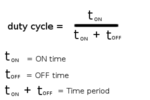
Microcontrollers are digital devices that understands binary signals, and the best representation of a binary signal is a square wave. The diagram below is a square wave showing the basic terminologies associated with a square wave signal. 


.

From the diagram above, it is  important to note that in a PWM signal  the TIME-PERIOD and hence the frequency is always fixed. Only the ON TIME and OFF TIME of the pulse i.e (duty cycle) varies. The term duty cycle describes the proportion of ON TIME to the regular interval or TIME PERIOD. With this, we modulate the given voltageThe difference between a square wave signal and PWM signal is that the square wave signal has same ON and OFF time (50% duty cycle), whereas a PWM signal has a variable duty cycle.
The square wave can be taken as a special case of the PWM signal which has 50% duty cycle (ON time = OFF time).
All microcontrollers features a set number of PWM pins. These are pins that have CCP (compare capture pwm).  PWM can be implemented using PIC MCU family. PIC 18F4458 is considered for the purpose of this write-up.


PWM Calculations

There are three crucial registers  must be taken into account for Pulse width modulation: PR2, and CCPRXL:CCPXCON[5:4]. Configuring the PR2 register, will allow you to configure the PWM period while selecting a proper the value for CCPRXL:CCPXCON[5:4] will allow you to choose the right duty cycle. For choosing the right value for the PR2 register, use the following equation…
PR2=\frac{PWM Period}{4*T_{osc}*TMR Prescale Value}-1
 Tosc is the the inverse of the frequency that your microcontroller is running at. Also, use a prescale of 16 . For CCPRXL:CCPXCON[5:4], we will use the following equation…
CCPRXL:CCPXCON[5:4]=\frac{PWM Duty Cycle}{T_{osc}*TMR Prescale}
CCPRXL:CCPXCON[5:4] is a 10 bit number. To make things easy make sure you convert your number to a 10 bit binary number. After you convert the number to a binary number, set your CCPRXL register to the first 8 MSB numbers. Finally, take the last 2 LSB and you use it for your CCPXCON[5:4]. Summary of the setup procedure for PWM operation  are found below:

1. Set the PWM period by writing to the PR2
register.
2. Set the PWM duty cycle by writing to the
CCPR1L register and CCP1CON<5:4> bits.
3. Make the CCP1 pin an output by clearing the
appropriate TRIS bit.
4. Set the TMR2 prescale value, then enable
Timer2 by writing to T2CON.
5. Configure the CCP1 module for PWM operation


Thursday, 8 August 2013

Getting down with PIC16F87X Microcontroller

Introduction
Embedded microcontrollers are everywhere in today's world, as you might know microcontroller and microprocessor  have substantially change our electronics lives . In an average household you will find them in cell phones, TV, calculators, remote control, air conditioner, microwave oven and MP3 players etc. Hardly  will any new appliance gets home without at least one controller. For example, in an  MP3 player, one controller could be for button and display, another for converting the music from digital format to something we can hear, etc. Nowadays, electronics device and circuit are mostly design as software running within microcontrollers, and these little devices can do so much beyond our imaginations. So electronics today are blend of hardware and software.
Microcontroller are simple to use, you don't need to be an expert in electronics before you start using them, all you need to get started is the basic understanding of electronics and digital circuits. Once you get your grips on it, that's it.
This write-up is  focused on  the overview of the PIC microcontroller internal architecture, describing the features of the 16F87X specifically.

What is a microcontroller?
Microcontrollers and microprocessors are integrated circuits, but they differ fundamentally from other ICs. The designers of microcontrollers have not made them to do a particular job. As such when
you buy them, you can not specify what function it will do, until you get home and configure it as you desire. Thus a microprocessor or microcontroller can be configured to check the status of a button, and then turn a motor ON or OFF. While the same IC can be configured later, to read the status of an infra-red sensor, decode the signal and turn another device ON or OFF. If these two types of circuits were to be made using conventional digital ICs, it would have required a large number of components. Moreover any change in the specification, like change of Infra-Red codes would result in total change in design.
The ability to configure microcontroller is called programming. A program is nothing but a series of instructions, in a correct and logical manner to instruct the microprocessor respond to various inputs. Microcontrollers are programmed to do a specific job, and these jobs could vary from changing TV channels to controlling industrial processes.

PIC Microcontroller
A company named Microchip® made its first simple microcontroller, which they called PIC. Originally this was developed as a supporting device for PDP computers to control its peripheral devices, and therefore named as PIC, Peripheral Interface Controller. Thus all the chips developed by Microchip® have been named as a class by themselves and called PIC.
The PIC16F87X is a family member of PIC CMOS FLASH-based 8-bit microcontrollers. It's upward compatible with the PIC16C5x, PIC12Cxxx and PIC16C7x devices. It features 200 ns instruction execution, 256 bytes of EEPROM data memory, self programming, an ICD, 2 Comparators, 8 channels of 10-bit Analog-to-Digital (A/D) converter, 2 capture/compare/PWM functions, a synchronous serial port that can be configured as either 3-wire SPI or 2-wire I2C bus, a USART, and a Parallel Slave Port.


Organisation of  PIC Microcontroller
The Figure above shows the pin out details of a very popular 40-pin PIC microcontroller, PIC16F87X, as you can see that each pin has been assigned a number of functions. Sometimes two and sometimes three. This situation is very common in microcontrollers, as there is always more which your microcontroller can offer, yet the number of pins on a given package is limited. In a given application a pin is usually tied to a specific job, and all functionality of a pin is usually not required, however you can use the specific pin your own way. The specific function of a pin is selected by configuring various bits of internal registers. The number and names of these special function registers (SFRs) vary from device to device as some devices have limited functionality while others have more. The selection and settings of these SFR’s is the key to successful programming. It is of best interest to go through the data sheets of the device before starting programming.

Features


High-Performance RISC CPU

Ø   Lead-free; RoHS-compliant
Ø   Operating speed: 20 MHz, 200 ns instruction cycle
Ø   Operating voltage: 4.0-5.5V
Ø   Industrial temperature range (-40° to +85°C)
Ø   15 Interrupt Sources
Ø   35 single-word instructions

Ø   All single-cycle instructions except for program branches (two-cycle)

Special Microcontroller Features

Ø   Flash Memory: 14.3 Kbytes (8192 words)
Ø   Data SRAM: 368 bytes
Ø   Data EEPROM: 256 bytes
Ø   Self-reprogrammable under software control
Ø   In-Circuit Serial Programming via two pins (5V)
Ø   Watchdog Timer with on-chip RC oscillator
Ø   Programmable code protection
Ø   Power-saving Sleep mode
Ø   Selectable oscillator options
Ø   In-Circuit Debug via two pins

Peripheral Features

Ø   33 I/O pins; 5 I/O ports
Ø   Timer0: 8-bit timer/counter with 8-bit prescaler
Ø   Timer1: 16-bit timer/counter with prescaler
Ø   Can be incremented during Sleep via external crystal/clock
Ø   Timer2: 8-bit timer/counter with 8-bit period register, prescaler and postscaler
Ø   Two Capture, Compare, PWM modules
Ø   16-bit Capture input; max resolution 12.5 ns
Ø   16-bit Compare; max resolution 200 ns
Ø   10-bit PWM
Ø   Synchronous Serial Port with two modes:
Ø   SPI Master
Ø   I2C Master and Slave
Ø   USART/SCI with 9-bit address detection
Ø   Parallel Slave Port (PSP)
Ø   8 bits wide with external RD, WR and CS controls
Ø   Brown-out detection circuitry for Brown-Out Reset
Ø   Analog Features
Ø   10-bit, 8-channel A/D Converter
Ø   Brown-Out Reset

PROGRAM MEMORY (FLASH): This is used for storing a written program. Since memory made in FLASH technology can be programmed and cleared more than once, it makes this microcontroller suitable for device development. 

EEPROM - This is a non-volatile data memory that are used in computer and other computerized system and which needs to be saved when there is no power supply. It is usually used for storing important data that must not be lost if power supply suddenly stops. For instance, one such data is an assigned temperature in temperature regulators. If during a loss of power supply this data was lost, we would have to make the adjustment once again upon return of supply. Thus our device looses on self-reliance. 


RAM- Data memory used by program during its execution. RAM stores all inter results or     temporary data during run-time. Ports are physical connections between the microcontroller and the outside world. PIC16F87X has five I/O ports and 33 pins in all 5 ports.


FREE-RUNTIMER  is an 8-bit register inside a microcontroller that works independently of the program. On every fourth clock of the oscillator it increments its value until it reaches the maximum (255), and then it starts counting over again from zero. As we know the exact timing between each two increments of the timer contents, timer can be used for measuring time which is very useful with some devices.

CENTRAL PROCESSING UNIT has a role of connective element between other blocks in the microcontroller. It coordinates the work of other blocks and executes the user program.

CISC, RISC
This term is related to computerised devices, and it needs to be explained here in more detail. Harvard architecture is a newer concept than von-Neumann's. It rose out of the need to speed up the work of a microcontroller. In Harvard architecture, data bus and address bus are separate. Thus a greater flow of data is possible through the central processing unit, and of course, a greater speed of work. Separating a program from data memory makes it further possible for instructions not to have to be 8-bit words. PIC16F87X uses 14 bits for instructions which allows for all instructions to be one word instructions. It is also typical for Harvard architecture to have fewer instructions than von-Neumann's, and to have instructions usually executed in one cycle. Microcontrollers with Harvard architecture are also called "RISC microcontrollers". RISC stands for Reduced Instruction Set Computer. Microcontrollers with von-Neumann's architecture are called 'CISC microcontrollers'. Title CISC stands for Complex Instruction Set Computer. Since PIC16F87X is a RISC microcontroller, that means that it has a reduced set of instructions, more precisely 35 instructions. (Ex. Intel's and Motorola's microcontrollers have over hundred instructions) All of these instructions are executed in one cycle except for jump and branch instructions. According to what its maker says, PIC16F87X usually reaches results of 2:1 in code compression and 4:1 in speed in relation to other 8-bit microcontrollers in its class.

REGISTERS
Special Function Registers
The Special Function Registers are registers used by the CPU and peripheral modules for controlling the desired operation of the device. These registers are implemented as static RAM. The Special Function Registers can be classified into two sets: core (CPU) and peripheral.

Status Registers
These registers contains the arithmetic status of the ALU, the RESET status and the bank select bits for data memory.The STATUS register can be the destination for any instruction, as with any other register. 

 USART
The Universal Synchronous Asynchronous Receiver Transmitter (USART) module is one of the two serial I/O modules. (USART is also known as a Serial Communications Interface or SCI.) The USART can be configured as a full duplex asynchronous system that can communicate with peripheral devices such as CRT terminals and personal computers, or it can be configured as a half duplex synchronous system that can communicate with peripheral devices such as A/D or 40 D/A integrated circuits, serial EEPROMs etc. The USART can be configured in the following modes:
• Asynchronous (full duplex)
• Synchronous - Master (half duplex)
• Synchronous - Slave (half duplex)

ANALOG-TO-DIGITAL CONVERTER (A/D) MODULE
The Analog-to-Digital (A/D) Converter module has five inputs for the 28-pin devices and eight for the other devices. The A/D conversion of the analog input signal results in a corresponding 10-bit digital number. The A/D converter has a unique feature of being able to operate while the device is in SLEEP mode. To operate in SLEEP, the A/D clock must be derived from the A/D‟s internal RC oscillator. The A/D module has four registers. These registers are:
• A/D Result High Register (ADRESH)
• A/D Result Low Register (ADRESL)
• A/D Control Register0 (ADCON0)
• A/D Control Register1 (ADCON1)

INTERRUPTS

The PIC16F87X family has up to 14 sources of interrupt. The interrupt control register (INTCON) records individual interrupt requests in flag bits. It also has individual and global interrupt enable bits. A global interrupt enable bit, GIE (INTCON<7>) enables (if set) all unmasked interrupts, or disables (if cleared) all interrupts. When bit GIE is enabled, and an interrupt‟s flag bit and mask bit are set, the interrupt will vector immediately. Individual interrupts can be disabled through their corresponding enable bits in various registers. Individual interrupt bits are set, regardless of the status of the GIE bit.

INSTRUCTION 

Each PIC16F87X instruction is a 14-bit word, divided into an OPCODE which specifies the instruction type and one or more operands which further specify the operation of the instruction. The PIC16F87X instruction set summary in byte-oriented, bit-oriented, and literal and control operations.
All instructions are executed within one single instruction cycle, unless a conditional test is true or the program counter is changed as a result of an instruction. In this case, the execution takes two instruction cycles with the second cycle executed as a NOP. One instruction cycle consists of four oscillator periods. Thus, for an oscillator frequency of 4 MHz, the normal instruction execution time is 1 μs. If a conditional test is true, or the program counter is changed as a result of an instruction, the instruction execution time is 2μs.

APPLICATIONS
PIC16F87X find it's place in most simple and complex microcontroller projects, some of these can be LCD, Access control and surveillance, Home automation, Digital display, Robotic and industrial instrumentation control projects.


Saturday, 3 August 2013

Low-power radio transmitters


Low-power radio transmitters

INTRODUCTION

Low-power transmitters has always been a fascinating one for hobbyists and experimenters.
They enable you to operate your own radio station, broadcast music, control
devices remotely without wires, do surveillance work, and other things such as remote sensing. Most of recent designs are based on FM, due to inevitable problems of AM transmission. These devices broadcast in the 88–108 MHz band and can have a range of several hundred feet when a sensitive receiver is used. FCC and NCC regulations limit range and field strength at a certain distance.
The modern low-power transmitters may employ varactor modulators, microprocessor-controlled frequency synthesis using a phase locked loop (PLL), audio preemphasis, audio mixing and control facilities, and stereo modulator circuitry that generates a “real” baseband multiplex signal. Integrated circuit (IC) devices make these tasks easily implemented with reasonable amounts of circuitry.

The following factors should be considered when designing transmitter:

1. Cost: Cost benefit analysis should be a determinant in choosing a specific solution.

2. Physical size: This may be an important factor, as in hidden surveillance camera in an aircraft, or even attached to a shirt pocket will be required to be small in size.
Obviously, such transmitters and their accessory components (e.g., battery,
microphone or other sensor, and antenna) have to be kept small, requiring surface-
mount construction techniques. Other applications may have few size
restrictions.

3. Power considerations: Available power might be limited, such as in hearing aid battery, or continuously available but limited, such as from a telephone
line, or unlimited for all practical purposes, as from a 120- or 240-volt
AC power line. The low-power transmitter will have to derive all of its operating
voltages from a specific source.

4. Type of emission (FM, AM, video, pulse, etc.): The transmitter design is determined
by these factors. Simple audio modulation or tone signals are relatively
easy, but video and other complex waveforms may require more complicated
circuitry with a higher component count.

5. Quality of transmission desired: Attributes such as audio or video quality, RF
output power, frequency stability, and range dictate the need for certain circuit
features. It may be possible or necessary to omit certain circuit elements and
features to obtain a certain goal, such as size, cost, or power consumption.
Certain factors, such as range of transmission or frequency stability, may mandate
other requirements. Often, compromises must be made.

6. Legal: FCC and NCC (Nigeria) rules dictate certain power, emission type, range, antenna, RF field strength, and frequency restrictions; however, in government,
police, or military work, these restrictions may not apply or are often ignored.

ARCHITECTURE

Some of the basic low-power transmitter architecture are as follows:

1. Basic Oscillator
      2. Master Oscillator-Power amplifier.
      3. Heterodyne mixer-Power amplifier


Build your home electronics lab: For beginners


  •  Build your own lab Do you want to build some electronic projects at home 
  •  Do you want to have a small homemade lab for your academic experiments  What do you will need to start building your own circuit 
  •  Tools and equipment you will need  are as follows:
  • 1. Small digital Multimeter DMM.
  • 2. Bread board Bread board to build your prototype circuits and test them.
  • 3. AC/DC 12v adaptor, this adaptor convert 220v AC to 12v DC to be your power supply for your circuit.
  • 4. Resistors, you will need some resistors with different values, these values are commonly used in beginners circuits. Values 330 1 K 4.7 K 10 K 22 K 47 K 100 K 1 M 100 K variable
  • 5. Capacitors, you will need some capacitors with different values, these values are commonly used in beginners circuits. Values 0.01 µF 0.1 µF 1 µF 4.7 µF 10 µF 47 µF 100 µF 220 µF 40 nF variable.
  • 6. Inductors, you will need some inductors with different values, these values are commonly used in beginners circuits. However the values available in the market are dependable on the market demand, so no values will be mentioned.
  • 7. Diodes You will need some diodes and full wave rectifiers to use in your power subcircuits. You can use these types of diodes in your circuit: 1N4001 and 1N4004.
  • 8. Full wave rectifiers They are the four rectifying diode bridge circuit in one package. Inputs are the ~ terminals and the outputs are the + & - terminals. Bridge part number W005 will be suitable but there is variety in this part so choose what you like to use. Get datasheets for other bridge parts from: www.datasheetcatalog.com
  • 9.. Zener diodes You may need zener diodes in your circuit, use zener 5v and zener 12v diodes.
  • 10. LED Sure you will need some LED’s as indicators in your circuit, but take care to connect a 330 or 1K resistor in series with the LED to protect it from over current and voltage. LED has no part number.
  • 11. Transistors, you will need some transistors to work on them. I recommend two types to work on them. Get datasheets of these transistors from: www.datasheetcatalog.com TIP41 power NPN BJT transistor 2N2222 NPN BJT transistor
  • 12. Voltage regulators. Voltage regulators are cheap IC’s used to regulate input voltage by lowering it from higher voltage to a lower constant voltage level, used for protecting electronic circuits. They look like power transistors. Terminals connection: 1: input voltage. 2:ground. 3: regulated output voltage 5v or 12v. Get there datasheets from: www.datasheetcatalog.com IC#: 7805 5v regulator and 7812 12v regulator
  • 13. 741 Operational amplifier Operational amplifier or shortly called Op-Amp is the basic building block for analog electronic systems, op-amp can perform many functions like amplifier, voltage summer, integrator, buffer and many other applications. use Op-amp IC# : 741, get its data sheet from: www.datasheetcatalog.com
  • 14. 555 timer/oscillator 555 is one of the famous IC in the electronics field, sure will use it in you circuits. It can function many tasks but the most famous function is square wave oscillator. Get 555 datasheet from: www.datasheetcatalog.com
  • 15. Logic gates If you are interested in digital electronics you ’d like to use logic gates. Mentioned in this table 74xx TTL logic family part numbers. Part number Description 7400 NAND 7402 NOR 7404 NOT 7408 AND 7432 OR 7486 XOR 7474 D-flip flop 7476 J-K flip flop 7448,7447 7 segment driver 7407 Open collector buffer
  • 16. Some other digital modules Mentioned in the table some other digital modules you would like to use. For more information get there datasheets from: www.datasheetcatalog.com Part number Description 74154 4x16 decoder 74151 8x1 Mux 7490 BCD counter 74393 Binary counter 74373 Tri-state latches 74245 Octal buffers
  • 19. Wires and connections You will wires to connect your circuit on the breadboard, I recommend to use Ethernet cable cause it little bit soft and be easily bended and reconfigured inside the circuit. These wires
  • 20. Tools you will need Wire cutter, Soldering iron, Screw drivers, Plier Soldering lead.